What Is Ceramic Radiant Tube Heating Wire?
Ceramic Radiant Tube Heating Wire is a resistance element designed to heat a ceramic tube, which then transfers energy outward as radiant heat. In industrial furnaces, this arrangement can warm a work area without exposing the element directly to combustion gases. Designs vary. Alloy, wire diameter, coil spacing, tube dimensions, and operating temperature all affect performance.
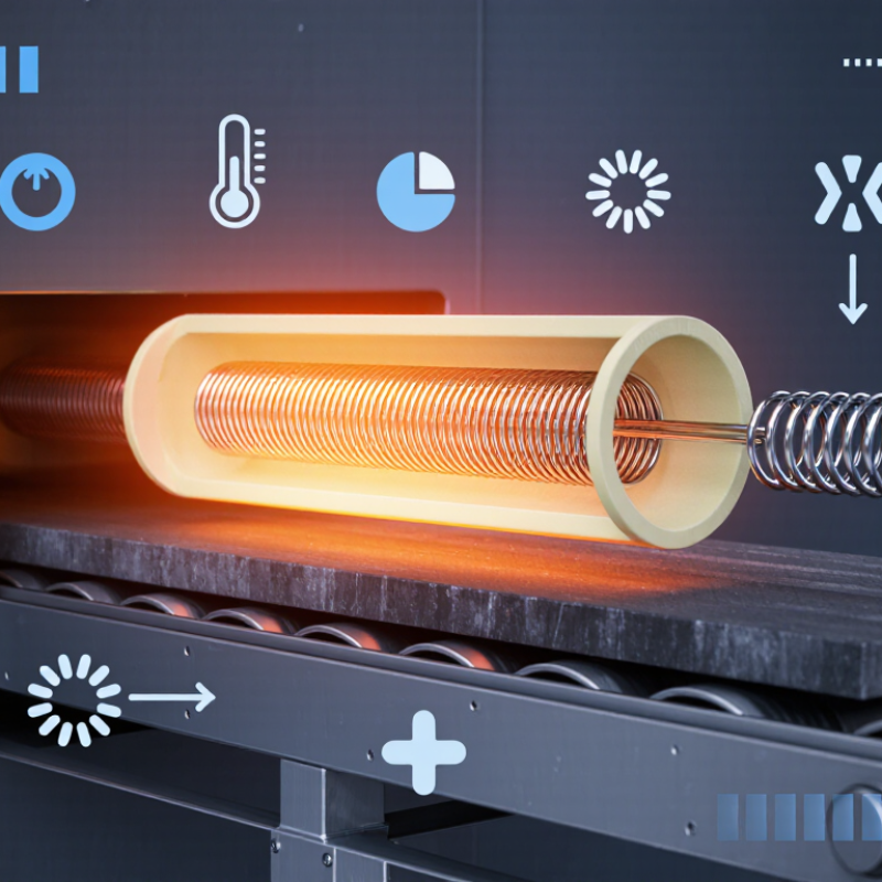
Inside a typical assembly, the wire is formed into a coil and supported within a ceramic radiant tube. When electrical current passes through it, the element heats the tube, which radiates energy toward nearby parts. Imagine a glowing tube above a moving steel component. Distance and surface condition matter. Small changes can alter heating uniformity. That distinction matters.
This article explains how the wire works, where it is used, and what to check when choosing a replacement or new assembly. Key details include rated voltage, wattage, maximum element temperature, tube compatibility, and the furnace’s control method. Manufacturer data should guide selection; appearance alone is not enough. Ceramic materials and resistance alloys have operating limits, and repeated thermal cycling can cause wear. No element lasts forever. Actual service life depends on installation, atmosphere, operating pattern, and maintenance. Catalog terms can also be imprecise, so confirm whether a supplier means the wire alone or the complete radiant-tube heater.
Definition and Purpose of Ceramic Radiant Tube Heating Wire
Ceramic radiant tube heating wire is an electrical resistance element fitted inside a ceramic radiant tube assembly. Its purpose is to convert electrical energy into heat. The hot element warms the tube, which then radiates heat toward nearby materials or a work area. It gets hot quickly.
The wire is commonly supported and electrically insulated by ceramic components that tolerate high temperatures. Exact construction varies by heater design, so the term does not describe one universal wire shape or material. In practical use, this arrangement can heat objects without direct contact with the heating element. That distinction matters in furnaces and other controlled heating processes. The tube’s condition, element spacing, and operating temperature all affect performance. A damaged ceramic support can also change how heat is distributed, so inspection should follow the equipment maker’s service guidance.
Tips: Check for cracks, discoloration, or loose supports before operation. Confirm the rated voltage and temperature range. Small details matter.
The name can be confusing: the wire produces heat, while the ceramic tube helps transfer it outward. Both parts need to suit the intended process.
Key Components and Ceramic Tube Structure
Ceramic radiant tube heating wire is the resistive element that converts electricity into heat. It sits within or along a ceramic support, depending on the heater’s design. Key components typically include the resistance wire, ceramic tube, electrical terminals, and supports that keep the wire positioned. Some assemblies also use insulation or a reflector to manage heat direction.
The ceramic tube is more than a cover. Its heat-resistant body supports the wire and helps spread radiant energy toward the target area. The tube may have a smooth bore, grooves, or other features that hold the element in place. Exact shapes and materials vary by operating temperature and equipment design. Even a small gap or uneven wire spacing can affect local heating. That detail is easy to overlook.
Tips: Check the tube for cracks and keep the wire evenly supported. Follow the heater’s rated voltage and temperature limits. A clean surface helps; dust buildup can change heat transfer. If a tube looks sound but heating remains uneven, inspect the element and connections before assuming the ceramic is at fault. Perfectly uniform heat is not always realistic.
How Electrical Energy Becomes Radiant Heat
What Is Ceramic Radiant Tube Heating Wire?
How Electrical Energy Becomes Radiant Heat
A ceramic radiant tube heating wire converts electrical energy into heat through electrical resistance. As current passes through the metal element, its resistance produces heat. The surrounding ceramic tube absorbs some of that energy, grows hot, and emits infrared radiation. That is the basic chain.
Radiation crosses the work area and warms surfaces directly. It may heat a metal part, moving web, or nearby fixture. Those surfaces then release heat into the surrounding air. Less waiting. Compared with air heating, the response can feel quicker, though results depend on tube layout, distance, and airflow.
In use, the wire’s temperature depends on its material, electrical input, and ceramic assembly. A controller can limit output, while careful spacing helps reduce cold zones. Do not assume every hot tube creates the same radiant pattern. Ceramic thickness, surface condition, and operating temperature matter. One detail is easy to overlook: an object may feel warm on one side and remain cooler on the other. Measure surface temperatures during setup; estimates alone can mislead.
Common Materials and Heating Wire Configurations
Ceramic radiant-tube heating wire is commonly made from nickel-chromium or iron-chromium-aluminium resistance alloys. Nickel-chromium wire is valued for stable resistance and workable forming; iron-chromium-aluminium wire is often selected for higher-temperature service. Resistance-alloy data summarized in ASM Handbook, Volume 1, place typical maximum element temperatures near 1,200°C for nickel-chromium and 1,400°C for iron-chromium-aluminium. These are material ratings, not guaranteed tube temperatures. Atmosphere, wire diameter, and heat loading change actual service life. Small differences matter.
The wire may be wound as a helical coil around ceramic supports, laid into grooves, or arranged in separate zones along the tube. A coil gives compact heating, while zoned layouts can help manage temperature differences along a long furnace chamber. In practice, installers should check spacing and support points: a sagging coil can create local hot spots. This detail is easy to miss. Ceramic composition and tube geometry also affect heat transfer, so alloy choice alone cannot predict performance. Treat handbook temperatures as a starting point, then verify the design against operating conditions and measured tube temperatures.
Applications, Operating Limits, and Selection Factors
Ceramic radiant tube heating wire is a resistance element that heats a ceramic tube, which then radiates heat toward a workpiece. This arrangement suits industrial furnaces, heat-treatment lines, and process ovens where direct flame contact is undesirable. It can provide steady, indirect heating. That matters when parts need a cleaner or more even thermal environment.
Operating limits depend on the wire alloy, tube material, element geometry, and surrounding atmosphere. A stated maximum temperature is not a universal working temperature. Long exposure near that limit can accelerate oxidation or shorten element life. Frequent starts, uneven airflow, and poor support can also create hot spots. Small details matter. Review the equipment maker’s temperature and power limits, and check whether the process atmosphere is compatible with both the wire and ceramic tube.
Selection should begin with the required furnace temperature, heating time, and usable tube length. Then confirm voltage, wattage, element spacing, and the control system’s switching range. A wire that reaches temperature quickly may still distribute heat poorly across a wide load. Allow clearance for thermal expansion, and check that replacement elements match the assembly rather than appearance alone. I would also question any selection based only on peak temperature; operating cycles and maintenance access often matter just as much.


