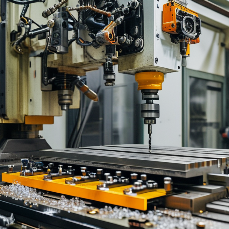
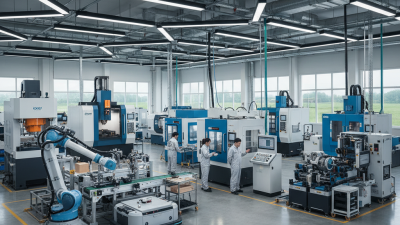
Machinery equipment quietly shapes modern work, from compact drills in a repair shop to automated systems in a food-processing plant. It converts energy, materials, and instructions into useful physical results. Some machines cut steel. Others lift heavy loads, package products, or control temperature with remarkable precision.
Elon Musk once described the factory as “the machine that builds the machine.” His observation shows why machinery equipment includes more than individual tools. It also involves motors, sensors, control software, safety guards, conveyors, and maintenance systems. These parts must cooperate. One weak connection can reduce productivity or create costly downtime.
A machine is never truly “automatic” without human judgment. Operators inspect unusual sounds, rising temperatures, loose bolts, and uneven movement. A worn bearing may produce a faint metallic hum before failure becomes obvious. That small detail can matter greatly. Engineers study load, speed, friction, power consumption, and operating conditions before selecting equipment. They also consider training, emergency controls, spare parts, and the working environment.
Still, no explanation covers every workshop. A machine that performs well in a clean factory may struggle in dust, humidity, or vibration. Manufacturers provide specifications, but real performance depends on installation and care. This is where practical experience challenges simple assumptions. Understanding how machinery equipment works requires technical knowledge, careful observation, and a willingness to question convenient answers. Efficient operation is valuable, but safe, maintainable, and responsible operation matters more.
Machinery equipment refers to powered machines, tools, and supporting systems that perform physical work. It may cut, lift, mix, press, transport, or assemble materials. In practical terms, a machine turns energy into controlled movement. That energy can come from electricity, hydraulics, compressed air, or fuel. The definition is not always tidy. A small workshop machine and a large production system can serve the same core purpose.
Most machinery equipment has several connected functions. The power source creates energy, while motors, pumps, gears, or cylinders transmit it. Controls guide speed, direction, pressure, and timing. Sensors can detect temperature, position, vibration, or overload. The working component then acts on the material. For example, a cutting machine may use a motor, drive system, clamp, blade, and control panel. Each part affects accuracy and safety.
Good machinery design also supports maintenance and operator protection. Guards reduce contact with moving parts. Emergency stops allow rapid shutdown. Lubrication points, inspection panels, and clear indicators help technicians find problems earlier. From workshop experience, unusual vibration often appears before a serious failure. However, diagnosis is not always simple. A loose fastener may imitate a damaged bearing. Regular records, careful testing, and trained judgment remain important. Machines are powerful, but they still depend on human decisions.
Machinery equipment converts energy into controlled movement, force, heat, or material flow. Its main types include rotating machinery, linear machines, fluid-handling systems, thermal equipment, and automated production units. Pumps move liquids. Compressors raise gas pressure. Motors create rotation, while actuators produce precise linear movement. According to the International Federation of Robotics’ World Robotics 2024 report, 541,302 industrial robots were installed worldwide in 2023. This figure shows how mechanical systems increasingly depend on coordinated motion and digital control.
Most machines share several structural components. A rigid frame supports the load and limits vibration. The power source supplies electricity, hydraulic pressure, compressed air, or fuel. Transmission parts, such as gears, belts, chains, and shafts, transfer torque. Bearings reduce friction around rotating shafts. Actuators deliver movement to the working tool, while sensors measure position, temperature, pressure, or speed. The controller interprets these signals and adjusts operation. Small details matter here. A loose coupling can damage an entire assembly.
Machine structure should match its working conditions. A dusty workshop may require sealed bearings and protected electrical cabinets. High-temperature equipment needs heat-resistant materials and controlled ventilation. ISO 12100 emphasizes risk reduction through design, guarding, and user information. Yet classification is not perfect. Many modern machines combine mechanical, electrical, and software systems. A robot, for example, is not only an arm; it also includes drives, feedback devices, safety circuits, and a carefully engineered frame. The frame looks simple, but it carries the consequences.
Machinery equipment converts stored energy into controlled motion. The source may be electricity, fuel, compressed air, or hydraulic pressure. An electric motor creates torque through magnetic fields. A shaft then transfers that torque to gears, belts, pumps, or cutting tools. In a workshop, this chain can feel simple: press start, and a spindle accelerates. The physics is less simple.
Energy losses occur at every connection. Bearings create friction. Gears produce heat. Belts can slip under sudden loads. The U.S. Department of Energy reports that motor-driven systems can represent more than half of industrial electricity consumption. Small efficiency improvements therefore matter across factories. A one-percent loss may seem harmless. Repeated thousands of hours, it becomes measurable cost and wasted energy.
Hydraulic equipment follows another route. An engine or motor drives a pump, which pressurizes fluid. Valves direct that pressure toward a cylinder. The cylinder extends, lifts, or clamps with high force. Compressed-air systems work similarly, but air leakage can quietly reduce performance. The International Energy Agency reported that industry used about 37% of global final energy in 2022, showing why conversion efficiency deserves close attention. Field technicians often check vibration, temperature, alignment, and pressure together. One reading rarely explains the fault. A warm bearing may signal poor lubrication, misalignment, or excessive load. The diagnosis can still be wrong. That uncertainty is part of practical engineering.
Machinery equipment converts electrical, chemical, hydraulic, or compressed-air energy into mechanical motion. The chart shows representative conversion efficiencies: the percentage of input energy that becomes useful mechanical output.
Typical engineering values are shown for comparison. The remaining energy is mainly released as heat, sound, vibration, fluid resistance, and friction. Actual efficiency depends on load, operating speed, maintenance, and design.
Machinery equipment combines mechanical parts, power transmission, sensors, and a control system. The control system acts as the equipment’s decision layer. Sensors measure speed, temperature, pressure, position, or vibration. A controller compares these readings with programmed limits. It then sends commands to motors, valves, or hydraulic actuators. For example, a conveyor may start slowly, maintain a fixed speed, and stop when a sensor detects a blocked section.
The workflow usually begins with a safety inspection. An operator checks guards, lubrication points, cables, and emergency-stop devices. The controller then confirms that essential conditions are safe. These conditions may include closed access panels and acceptable motor temperature. During operation, the system continuously processes incoming data. An interface displays running speed, load level, and active alarms. If vibration rises sharply, the controller may reduce speed or stop the machine. Small errors matter.
Good operation depends on both automation and human judgment. Maintenance teams review sensor records, inspect worn bearings, and test calibration at planned intervals. A warning signal does not always identify the real cause. A dirty sensor can imitate a serious mechanical fault. This is where practical experience becomes important. Technicians compare digital readings with sound, heat, movement, and visible wear. The workflow is rarely perfect. Delayed maintenance, unclear alarm messages, or rushed inspections can weaken reliable performance. Clear procedures and honest records help reveal these weaknesses before they become expensive failures.
| Equipment Type | Primary Function | Typical Power or Capacity | Main Control System | Common Sensors | Typical Operating Workflow | Key Safety Controls | Typical Output or Performance Measure |
|---|---|---|---|---|---|---|---|
| CNC Milling Machine | Removes material from a workpiece to produce precision components. | 5–50 kW spindle power; positional accuracy commonly within 0.01–0.05 mm, depending on machine design and conditions. | Computer numerical control with programmed tool paths, servo drives, and motion interpolation. | Position encoders, spindle-load sensors, tool-length probes, coolant-level sensors, and door switches. | Part setup → work coordinate setting → program loading → tool verification → cutting cycle → inspection and correction. | Guard interlocks, emergency stop, overspeed protection, collision monitoring, and automatic tool-area shutdown. | Dimensional accuracy, surface finish, machining time, material-removal rate, and scrap percentage. |
| Hydraulic Press | Applies controlled compressive force for forming, stamping, bending, or assembling materials. | Approximately 10–1,000+ tonnes of rated pressing force, depending on the equipment class. | Programmable logic controller with hydraulic valves, pressure regulation, and position control. | Pressure transducers, linear position sensors, temperature sensors, and ram-limit switches. | Load material → close guarding → advance ram → reach programmed pressure or position → hold → retract → unload. | Two-hand controls, light curtains, pressure relief valves, guarded tooling, and emergency-stop circuits. | Pressing force, stroke position, cycle time, forming accuracy, and completed parts per hour. |
| Belt Conveyor | Moves bulk materials, packages, or components between process stations. | Common belt speeds of 0.3–3 m/s; capacity varies widely with belt width, material density, and loading method. | Motor starter or variable-frequency drive controlled by a PLC or distributed control system. | Speed sensors, belt-alignment switches, pull-cord switches, motor-current sensors, and blockage detectors. | Material loading → belt acceleration → continuous transport → transfer or discharge → inspection and shutdown. | Emergency pull cords, belt misalignment trips, overload protection, nip-point guarding, and controlled restart logic. | Throughput in tonnes per hour or units per minute, belt availability, transfer efficiency, and downtime. |
| Centrifugal Pump | Transfers liquids by converting rotating impeller energy into fluid pressure and flow. | Typical flow ranges from a few L/min to several thousand m³/h; operating pressure depends on pump design and speed. | Motor starter or variable-frequency drive with pressure, flow, and level-based control. | Discharge-pressure sensors, flowmeters, suction-pressure sensors, vibration sensors, and motor-temperature sensors. | Prime or fill system → open required valves → start motor → stabilize flow → monitor pressure and vibration → controlled stop. | Dry-run protection, relief or bypass arrangements, overcurrent protection, seal monitoring, and high-vibration shutdown. | Flow rate, differential pressure, hydraulic efficiency, power consumption, and mean time between failures. |
| Screw Air Compressor | Produces compressed air for pneumatic tools, actuators, instrumentation, and process equipment. | Approximately 5–500 kW motor power; common working pressures are about 7–13 bar. | Microprocessor controller or PLC managing inlet modulation, load/unload operation, and pressure sequencing. | Discharge-pressure sensors, air-temperature sensors, oil-temperature sensors, separator differential-pressure sensors, and motor-current sensors. | Start lubrication system → accelerate motor → load air end → regulate pressure → unload at setpoint → cool and stop. | High-temperature trip, overpressure protection, oil-level monitoring, motor overload protection, and emergency stop. | Free air delivery, discharge pressure, specific energy consumption, air quality, and compressor availability. |
| Industrial Robotic Arm | Performs repeatable handling, welding, assembly, painting, or inspection tasks. | Typical payloads range from 3–500 kg; reach commonly ranges from about 0.5–3.5 m. | Dedicated robot controller with servo drives, programmed paths, and supervisory PLC communication. | Joint position encoders, motor-current sensors, end-effector sensors, vision cameras, and safety-gate switches. | Home position → receive task signal → pick or process part → move along programmed path → place or complete operation → verify result. | Safety-rated monitored stop, protective fencing, interlocked gates, reduced-speed teaching mode, and emergency stop. | Cycle time, repeatability, payload utilization, first-pass yield, and operating availability. |
| Industrial Boiler | Generates steam or hot water for heating, processing, sterilization, or power-related applications. | Capacity is commonly specified in kg/h or MW; operating pressure varies significantly by boiler type and application. | Burner management system and PLC or distributed control system regulating fuel, air, water level, and steam pressure. | Steam-pressure sensors, water-level probes, flame detectors, oxygen sensors, temperature sensors, and flowmeters. | Pre-purge → ignition → flame verification → controlled firing → water-level regulation → steam delivery → shutdown or standby. | Low-water cutoff, flame-failure trip, pressure-relief valves, fuel shutoff valves, and combustion-air monitoring. | Steam generation rate, thermal efficiency, fuel consumption, emissions, pressure stability, and availability. |
| Diesel Generator Set | Converts fuel energy into electrical power for standby, prime, or remote power applications. | Common ratings range from approximately 10 kVA to several MVA; actual output depends on duty rating and site conditions. | Engine governor and automatic generator controller managing voltage, frequency, synchronization, and load sharing. | Oil-pressure sensors, coolant-temperature sensors, fuel-level sensors, speed pickups, voltage transformers, and current transformers. | Start command → pre-lubrication or cranking → engine start → voltage and frequency build-up → load transfer → monitoring → cooldown and stop. | Overspeed trip, low-oil-pressure shutdown, high-coolant-temperature shutdown, circuit protection, and automatic transfer interlocks. | Electrical output, fuel consumption per kWh, voltage stability, frequency stability, load factor, and start reliability. |
| Forklift Truck | Lifts, transports, and positions palletized or unit loads within a controlled work area. | Typical rated capacities range from 1–10 tonnes; lift height depends on mast configuration and load rating. | Electro-hydraulic control system using operator inputs, traction control, and hydraulic valve control. | Load sensors, mast-height sensors, seat switches, steering-angle sensors, battery or fuel sensors, and speed sensors. | Pre-use inspection → load approach → fork insertion → lifting → controlled travel → placement → lowering → parking. | Seat-belt interlocks, load backrest, horn, speed limiting, parking brake, stability triangle principles, and rated-capacity limits. | Load-handling cycles per hour, travel speed, energy or fuel use, uptime, and incident-free operating hours. |
| Packaging Machine | Forms, fills, seals, labels, or groups products into transport-ready packages. | Typical speeds range from about 20 to 600 packages per minute, depending on product and machine configuration. | PLC with servo motion control, human-machine interface, recipe management, and quality-check logic. | Photoelectric sensors, product-presence sensors, temperature sensors, pressure sensors, encoder feedback, and seal-quality sensors. | Product feeding → package forming → filling or loading → sealing → coding or labeling → inspection → discharge. | Guard-door interlocks, jam detection, temperature limits, emergency stops, and automatic rejection of defective packages. | Packages per minute, fill accuracy, seal integrity, material waste, changeover time, and overall equipment effectiveness. |
Maintenance, Safety, and Industrial Applications
Machinery equipment converts energy into controlled movement, pressure, heat, or material flow. Motors drive pumps, gears transfer torque, and sensors reveal changing conditions. In a working plant, maintenance is less about fixing old parts than protecting process stability. Technicians inspect vibration, temperature, lubrication, alignment, and unusual noise. A hot bearing may sound harmless during a busy shift. It is not.
The U.S. Department of Energy’s Operations and Maintenance Best Practices Guide reports that predictive maintenance can reduce costs by 8–12% compared with preventive maintenance and 30–40% compared with reactive maintenance. These figures are useful benchmarks, not promises. A sensor can also lie. Calibration, clean data, and experienced review still matter.
Safety must be built into industrial applications, from conveyors and compressors to packaging and water-treatment systems. Before servicing, workers should isolate electrical, hydraulic, pneumatic, thermal, and stored mechanical energy.
OSHA estimates that effective lockout/tagout practices prevent about 120 fatalities and 50,000 injuries each year in the United States. Guards, interlocks, emergency stops, and clear access routes provide additional protection.
Yet procedures often weaken when production pressure rises. A practical inspection should ask what happens after a power return, jam, or rushed handoff. Maintenance records should show the defect, action, measurement, and responsible person. ISO 55001 frames asset management around value, risk, and performance, rather than equipment age alone. A rushed handoff can undo excellent engineering.
JK Machinery a.s.
Psohlavců 322/4, Praha 4,
Czechia
T: +420 777 610 380
E: sale@roll-formingmachinery.com