Choosing the right capacitor is more than matching a number on a schematic. It requires understanding voltage, frequency, ripple current, temperature, lifetime, and physical space. In real designs, a capacitor may sit beside a hot regulator or near a noisy motor. Its environment matters.
The broader field of Capacitors And Capacitance connects electrical theory with practical engineering judgment. Dr. Arthur von Hippel, a pioneer in dielectric research, stated, “The dielectric is the heart of the capacitor.” This principle remains valuable because the dielectric affects leakage, stability, losses, and long-term reliability. A ceramic capacitor may provide low inductance, while an aluminum electrolytic capacitor often offers high capacitance economically. Neither choice is automatically better.
The correct capacitance value is only one part of the decision. Engineers must check the rated voltage with suitable margin, especially where spikes occur. Ripple current can create heat. High equivalent series resistance can weaken filtering performance. Temperature can also reduce capacitance or shorten service life. Small details become expensive failures.
No chart is perfect. Even experienced engineers miss a detail sometimes. A first choice may be wrong after testing. That is why this guide compares capacitor types, capacitance ratings, tolerances, ESR, safety requirements, and application conditions. The goal is not simply to select a component that works today. It is to choose one that remains stable, safe, and dependable throughout the product’s expected life.
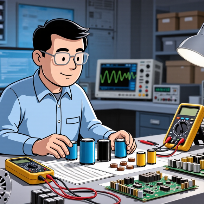
Start with the application voltage. Measure the highest normal voltage, including startup surges and switching spikes. Select a rated voltage above that value, not equal to it. Many engineers keep 20–30% voltage margin, although harsh circuits may require more. IEC 60384-1 emphasizes rated voltage, temperature, endurance, and reliability testing for fixed capacitors.
Temperature matters. A capacitor near a hot heat sink may lose capacitance faster than expected. My early design mistake was checking only the printed voltage rating. That shortcut was wrong.
Frequency determines impedance. Use Xc = 1/(2πfC) to estimate capacitive reactance.
At 60 Hz, a 10 µF capacitor has about 265 ohms of reactance. At 10 kHz, the same part falls below 2 ohms.
Switching supplies also create ripple currents, so capacitance alone cannot define performance. Check ripple-current ratings, ESR, and self-resonant frequency.
IEEE 519-2022 commonly uses a 5% total voltage-distortion limit for low-voltage systems at the point of common coupling. Harmonic currents can heat capacitors unexpectedly.
Estimate capacitance from load behavior, not habit. For smoothing, calculate allowable ripple voltage and load-current changes. For motor correction, include system frequency and harmonic conditions.
The International Energy Agency reported that global electricity demand increased 2.2% in 2023 and may grow about 3.3% annually through 2026. More electronic loads mean more switching noise and distortion.
A capacitor that works on a quiet bench may struggle in a crowded panel.
Recheck measurements after installation. Reality is less tidy.
Capacitance tolerance is not a minor detail when a circuit depends on accurate timing, filtering, or sensing. A 10% capacitor may deliver 90 to 110 nF from a 100 nF specification. That range can shift oscillator frequency or alter a filter’s cutoff point. For stable signal paths, choose a low-loss dielectric with a 10% tolerance when available. C0G or NP0 materials usually maintain capacitance well across temperature and voltage. They suit precision timing and measurement circuits.
For general decoupling, a 20% tolerance may be acceptable, especially when the circuit has wide operating margins. High-capacitance ceramic parts can lose capacitance under applied DC voltage, so check the bias curve, not only the label.
Electrolytic capacitors often carry tolerances near 20% or 30%, with aging and temperature adding more variation. Expect drift. Use them for bulk energy storage rather than precision timing. Film capacitors can provide dependable stability, although their physical size may increase at higher capacitance values.
A practical selection starts with the circuit’s worst-case limits. Measure a sample at operating temperature and voltage. I have seen designs pass room-temperature testing, then fail after a warm-up period. That mistake is easy to make. It also deserves honest review: a narrower tolerance does not guarantee better performance if leakage, aging, or dielectric absorption dominates. Verify the datasheet conditions and leave useful margin around the required capacitance.
How to Choose Capacitors and Capacitance for Your Needs?
Check Rated Voltage with the 20% Derating Rule for Reliability
A capacitor’s rated voltage should exceed the highest voltage in your circuit. The 20% derating rule offers a practical starting point. Operate the capacitor at no more than 80% of its rated voltage. For a steady 12-volt rail, choose at least a 15-volt capacitor. A 16-volt part gives slightly more breathing room.
Do not stop there. Voltage spikes, switching noise, temperature, and ripple current can reduce reliability. Electrolytic capacitors may have shorter lives near their maximum temperature. Ceramic capacitors can lose capacitance under DC bias. Check the datasheet, not only the printed value. This is where designs often become less simple. A capacitor that looks suitable on paper may perform poorly during testing. I would recheck the real waveform with an oscilloscope, because assumed voltage is sometimes wrong.
Tips: Measure both normal voltage and startup spikes. Keep extra voltage margin in harsh environments. Confirm polarity before powering the circuit. Compare capacitance at the actual operating voltage. If the circuit is safety-critical, ask a qualified engineer to review the selection. The 20% rule is helpful, but it is not a complete design method. Reconsider it when ripple, heat, or rapid switching becomes significant.
Select a capacitor with a rated voltage comfortably above the maximum expected circuit voltage. Applying a 20% derating rule means keeping the normal operating voltage at or below 80% of the capacitor's rated voltage. The chart compares common rated-voltage options with their recommended maximum operating voltage.
How to Choose Capacitors and Capacitance for Your Needs?
Capacitance alone rarely determines capacitor performance. At 100 kHz, a capacitor’s ESR, ESL, and impedance shape the actual filtering result. IEC 60384-1 defines electrical and endurance tests for fixed capacitors, while EIA-456-A addresses ripple-current life evaluation for aluminum electrolytic types. These standards remind engineers to compare tested conditions, not only catalogue values. A 10 µF part with 20 mΩ ESR dissipates 0.08 W at 2 A RMS ripple, calculated from I²R. That heat remains inside a compact enclosure. Small numbers become real temperature.
Measure impedance at the circuit’s operating frequency. A capacitor rated at 1 kHz may perform poorly at 500 kHz. Its impedance can rise after self-resonance, even when capacitance looks correct. Published reliability studies in IEEE power-electronics literature often identify ripple heating and temperature as dominant ageing factors. A practical design review should record ambient temperature, switching frequency, RMS ripple, and expected service hours. Use an impedance analyzer if possible. Oscilloscope checks can expose unexpected voltage spikes. Do not trust one test.
There is room for caution. Datasheet ripple ratings often assume specific airflow, frequency, and temperature. Your enclosure may be less forgiving. I would derate ripple current by 20–30% during early prototypes, then confirm thermal behavior experimentally. That choice is conservative, not universal. Measure the can temperature, inspect waveform distortion, and reassess capacitance after stress testing.
Choosing a capacitor starts with its working environment, not its capacitance value. Confirm a temperature rating from −55°C to 125°C when equipment faces cold storage, engine heat, or outdoor exposure. Under the applicable IEC 60384 specification, check the declared category temperature range and test conditions. Do not treat “125°C” as a guarantee of equal performance across that entire range.
Temperature changes affect capacitance, leakage current, insulation resistance, and service life. A capacitor rated for 125°C may need voltage derating near its upper limit. Review ripple-current limits at the actual ambient temperature. Also check tolerance, frequency behavior, and DC bias, especially in filtering or timing circuits. During testing, place a thermocouple near the component body. Small layout changes can create surprising heat. I have seen a safe-looking design fail because airflow was measured several centimeters away.
Tips: Compare the datasheet’s temperature curves, not only its headline rating. Confirm endurance hours at the intended voltage and temperature. Leave thermal margin when possible. A −55°C requirement may also demand suitable seals, leads, and mechanical mounting. This detail is easy to overlook. If the application repeatedly cycles between freezing and hot conditions, test real samples through those cycles. Laboratory assumptions can be too optimistic. Record capacitance before and after testing, then inspect leakage and physical damage.
JK Machinery a.s.
Psohlavců 322/4, Praha 4,
Czechia
T: +420 777 610 380
E: sale@roll-formingmachinery.com