Industrial equipment rarely operates in a quiet electrical environment. A motor starts, a variable-frequency drive switches, and nearby sensors must keep reporting reliable measurements. In that setting, choosing an Industrial EMC Solution is not just a matter of adding a filter or shield. The right approach depends on the equipment, the installation, and the interference paths that testing reveals.
EMC authority Henry W. Ott’s published guidance can be paraphrased this way: “Build compatibility into the design; do not leave it to last-minute fixes.” That principle matters when selecting cables, enclosures, filters, grounding methods, and installation practices. A shielded cable, for example, may offer little benefit if its termination is poor. Details matter.
The seven tips ahead will help teams assess risks, compare solution types, and check performance under realistic operating conditions. They also encourage early collaboration between design, purchasing, and installation teams. Keep the site conditions in view: cable lengths, cabinet layout, nearby drives, and maintenance access can all affect results. No single product solves every EMC problem. And a clean bench test is not always enough. Some choices will involve trade-offs, and early assumptions may need revisiting. That is not failure; it is part of making a reliable, evidence-led decision.
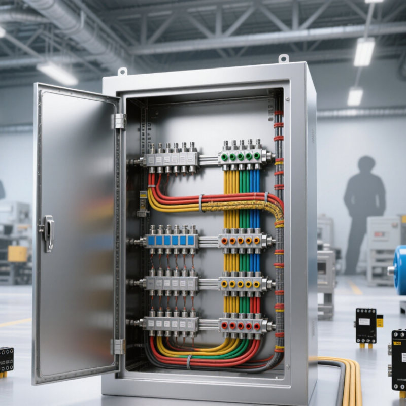
Before choosing an industrial EMC solution, describe the failure in observable terms. Does a controller reset when a motor starts, or does a sensor reading drift near a variable-speed drive? Record the affected equipment, operating state, cable routes, enclosure condition, and timing. A phone photo of cable bundles and cabinet entry points can reveal details a fault log misses. Our first notes are often incomplete. That is worth correcting before specifying filters or shielding.
Map the operating environment as carefully as the symptom. Note nearby transmitters, switching loads, long sensor leads, grounding connections, dust, moisture, and temperature changes. IEC 61000-4-3 specifies radiated RF immunity test methods across 80 MHz to 6 GHz; IEC 61000-4-6 covers conducted RF disturbances from 150 kHz to 80 MHz. These are test ranges, not a diagnosis of the noise at your site. Measure during the actual fault, if possible, and compare results with normal operation. A quiet bench test can mislead. The cable route may be the real clue. Tie each observed disturbance to a frequency, location, and machine state before selecting a remedy.
Interference mapping should begin at the equipment, not the catalogue. Record when faults occur: during motor starts, contactor switching, or inverter speed changes. Note affected devices, cable routes, and operating states. A sensor that resets beside a long motor cable may face conducted or radiated noise. A nearby radio transmitter can create a different exposure. Start there.
IEC 61000-4-3:2020 defines radiated RF immunity test levels from 1 to 30 V/m; Level 3 is 10 V/m. IEC 61000-4-4:2012 specifies Level 3 fast-transient tests of 2 kV on power ports and 1 kV on signal ports. These are useful benchmarks, not proof that a test setup matches a plant floor. That matters. Compare equipment test records with measured site conditions, cable lengths, grounding, and enclosure openings. Use a spectrum analyzer or current probe during the fault window, and log machine states. A clean measurement on a quiet shift can mislead. Test the actual vulnerable input, especially long sensor lines and communication ports, before selecting filters or shielding.
| Tip | Interference source to investigate | Potentially susceptible equipment | Typical clues | How to identify or verify | Practical first response |
|---|---|---|---|---|---|
| 1. Map the noise sources | Variable-speed drives, servo drives, switching power supplies, relay coils, contactors, and arc-producing equipment. | PLC inputs, analog sensors, encoder circuits, communication interfaces, and weighing or measurement systems. | Faults or unstable readings appear when a particular machine starts, stops, or changes operating speed. | Record when symptoms occur; compare them with machine events. Inspect cable routes and use suitable current or field probes to locate noisy circuits. | Separate noisy power wiring from control and signal wiring. Confirm bonding and cable-screen connections before adding filters. |
| 2. Check conducted interference paths | Noise coupled onto power, signal, or grounding conductors by switching loads, drives, or shared supplies. | Equipment sharing the same supply, long sensor loops, and devices connected to common control or communication wiring. | Several devices misbehave together, or a problem changes when a load is switched or an electrical connection is rerouted. | Inspect supply and signal wiring, grounding topology, and cable shields. For formal investigations, conducted-emissions measurements commonly examine the 150 kHz–30 MHz range, subject to the applicable test standard. | Review circuit separation and bonding; consider a correctly rated line filter or signal isolation where measurements show it is appropriate. |
| 3. Look for radiated coupling | Fast-switching power electronics, high-current conductors, radio transmitters, and poorly contained electrical arcs. | Unshielded sensor wiring, high-impedance inputs, wireless or radio equipment, and devices with exposed or long interconnects. | Interference depends on distance, enclosure doors, cable position, or the operating state of a nearby source. | Compare behavior at different distances and cable positions. Use a near-field probe or an appropriate EMC test setup to locate emissions; test ranges depend on the product standard. | Reduce loop area, improve enclosure bonding, and route sensitive cables away from high-current or fast-switching circuits. |
| 4. Assess susceptibility by function | Electrostatic discharge, fast transients from switching, surges, conducted RF, or radiated RF. | Reset-sensitive controllers, safety-related controls, low-level analog inputs, and communication ports. | Unexpected resets, false input transitions, corrupted data, or loss of communication occur during disturbances. | Review equipment documentation and applicable immunity requirements. Relevant IEC 61000-4 test methods include ESD (-4-2), electrical fast transient/burst (-4-4), and surge (-4-5). | Match protection to the disturbance and port: options may include suitable transient protection, filtering, shielding, or galvanic isolation. |
| 5. Inspect cable and port details | Common-mode currents on cable shields, poor connector termination, long unshielded pigtails, and cable-entry gaps. | Ethernet, fieldbus, encoder, thermocouple, and other low-level or high-speed signal interfaces. | Faults change when a cable is touched, replaced, rerouted, or connected to a different port. | Check cable type, connector pinout, shield continuity, termination method, and the installation guidance for both connected devices. | Use compatible cables and connectors; terminate shields and bond enclosures as specified by the equipment design and site grounding plan. |
| 6. Verify the installation environment | Shared trays, long parallel cable runs, poor equipotential bonding, and noisy power distribution. | Remote I/O, distributed sensors, control cabinets, and equipment connected across separate structures or panels. | Intermittent issues vary by route, shift, equipment configuration, or connection between cabinets. | Document cable routes, lengths, tray sharing, enclosure bonds, and supply connections. Compare affected and unaffected installations or routes. | Improve routing and separation, maintain low-impedance bonding, and follow the equipment manufacturer's installation instructions. |
| 7. Test the fix under real operating conditions | Combined disturbances from multiple sources, especially during startup, braking, switching, or high-load operation. | Any equipment that must remain reliable during normal production and foreseeable electrical disturbances. | A change appears to work at idle but faults return when multiple machines operate or production conditions change. | Repeat checks across operating modes, loads, and relevant cable configurations. Record symptoms, measurements, and test conditions before and after changes. | Choose a solution supported by measured evidence, then verify that it does not compromise safety, protective bonding, signal integrity, or applicable compliance requirements. |
Note: These are general troubleshooting examples, not universal limits or a substitute for equipment-specific documentation, risk assessment, or testing to the applicable standards.
Industrial EMC problems rarely have one universal fix. Filtering reduces unwanted electrical noise traveling through power or signal lines. Shielding limits electromagnetic energy entering or leaving an enclosure. Grounding provides a controlled reference and path for fault or interference currents. Each works differently, so compare the noise path before choosing a solution. A filter may quiet a power input but cannot repair a poorly bonded panel seam. Placement matters.
Shielding depends on material, coverage, and continuity. A small gap around a door or cable entry can weaken an otherwise solid enclosure. Grounding also needs deliberate design: long, narrow connections may add impedance where a short, wide bond works better. Keep sensitive signal wiring away from noisy power cables. Check the seams. It is easy to focus on the enclosure and overlook connectors or cable routing.
Tips: Identify whether interference travels through cables or radiates through space. Choose filtering for conducted noise, and verify its current and frequency ratings. Use shielding when enclosure openings or exposed circuits are vulnerable. Bond shield panels across clean, bare contact surfaces. Keep grounding connections short and wide. Test cable entries and door seams, not just the main enclosure. Recheck the full assembly under operating conditions; a fix that works on the bench may behave differently after installation.
Before selecting an industrial EMC solution, identify the standards that apply to the equipment and its destination. IEC 61000 tests cover several immunity and emissions concerns, but the relevant parts depend on the product and operating environment. Check the equipment specification, test reports, and customer requirements together. A standard named in a brochure is not proof that the complete installation meets it. Details matter.
Compatibility starts with the electrical system. Confirm voltage, current, frequency, grounding method, and the types of interference present. A drive cabinet beside a long motor cable may need different filtering from a sensor panel in a quiet control room. Check connector types and cable shielding, too. A solution that fits electrically can still perform poorly if its filter is mismatched to the noise path. This is easy to overlook.
Installation requirements deserve equal attention. Measure available panel space and confirm mounting orientation, clearances, temperature limits, and access for maintenance. Keep input and output wiring separated where the instructions require it, and use short, secure bonding connections. In practice, cramped enclosures often force compromises. That is worth reviewing before purchase, not after a failed test. Record the proposed layout and verify it against the manufacturer’s technical documentation and the equipment test plan.
IEC 61000-4-4 defines test levels of 0.5, 1, 2, and 4 kV for electrical fast transient/burst immunity. The appropriate level depends on the applicable product standard, port, and installation environment. Check these requirements alongside compatibility and installation needs before selecting an EMC solution.
An industrial EMC solution should be tested in the conditions it will actually face. Check emissions and immunity with the production enclosure, cable lengths, grounding points, and typical operating loads in place. A quiet bench setup may miss interference caused by a motor starting or a long sensor cable. Small details matter. Record the test method, equipment settings, and results so later checks can be compared fairly.
Tip: Test near realistic worst-case conditions, then repeat key checks after installation. Keep the setup consistent. If a result changes, inspect cable routing, connector seating, and bonding before replacing equipment. A rushed retest can look reassuring, but it may hide a setup difference; that is easy to overlook.
Performance also depends on maintenance. Include EMC-related checks in scheduled inspections: look for loose fasteners, damaged cable shields, corrosion at bonding points, and added wiring that crosses sensitive signal lines. After repairs or control-panel changes, review whether the original test still represents the installation. Keep dated records of faults, adjustments, and retest results. These notes help technicians identify gradual changes instead of treating each interference event as a new mystery. Regular checks cannot prevent every problem, but they make performance easier to verify.
JK Machinery a.s.
Psohlavců 322/4, Praha 4,
Czechia
T: +420 777 610 380
E: sale@roll-formingmachinery.com